Can a Capacitor Generator Be Converted to a Automatic-voltage-regulator Generator
Voltage regulator for brushless synchronous generator
with harmonic excitation winding
 When I prepare my home in what some people like to call "wilderness", I built a microhydro organization to provide for all the energy needs in my home. For this purpose I bought two generators, to use one permanently and have the other as a spare, to be swapped in case of serious problem.
 The chosen generators are of the Chinese TFDW blazon. These come with an AVR, that is, an "automatic voltage regulator". In 11 years of continous utilise, I have had three failures of those AVRs. The first one happened due to a voltage transient caused by a nearby lightning hit, which killed that AVR merely very little else, because the original AVR was (mis)designed in such a fashion that it is extremely sensitive to transients. That time I swapped the dead AVR for the i in my spare generator, and then tried to take apart the expressionless one, to either fix it or re-create information technology. They come potted in hard black epoxy resin, which is great to avert failure from vibration, merely nasty when it comes to repairing. I managed to take it apart, using a lot of heat, patience and brute force, but afterwards opposite-engineering it I found its design to be and so poor that information technology wasn't a good idea to repair information technology, let alone build a copy.
I ordered two new AVRs from Red china. They are very inexpensive. The trouble is that none are available that fit the TFDW generator really well. The closest fit is one made for the ST line of generators, which are brush-blazon machines, merely at least use the same excitation winding system as the TFDW. So I bought two GB-160 AVRs, but unfortunately they don't work correctly with the TFDW generators. The combination is unstable, making the output voltage oscillate by several tens of volts at roughly 3Hz.
Presently subsequently the second original AVR failed, and this fourth dimension there was no external cause. Simply its niggling power transformer burned out. Small 50Hz transformers have thousands of turns of very thin wire, which tends to corrode at the soldered ends, due to tiny residues of corrosive flux, or only oxygen and wet in the air. Given the emergency I had to install one of the new GB-160 AVRs, and alive with dramatically flickering lights and a dancing refrigerator, while I stock-still the failed AVR. I had to find a suitable transformer for it, and I had to remove its electronic lath from its metallic vanquish, which I did by heating the trounce with a blowtorch, to quickly soften the epoxy between the board and the vanquish earlier overheating the components. Information technology worked, enabling me to remove the lath, and supersede the dead transformer on it.
2 years after this AVR started failing again, in a gradual manner. The regulation got ever worse, it got e'er more than sensitive to load transients, very probable due to failing electrolytic capacitors. It has several of them, installed very close to power resistors and other parts that get hot. That's a sure recipe for failure afterward some years of employ.
At that point I decided to finally blueprint my own AVR for this generator. I built it into the beat out of the first original AVR, with the terminal block at the aforementioned identify, for all-time mechanical compatibility. The event is what you can encounter in the title photo.
Dynamics of brushless generators
Conventional brush-type generators are simple animals: A DC-powered field winding rotates inside a stator, which tin have a single-phase or a three-stage winding. The DC is applied to the field via carbon brushes and sliprings. At the rated speed, roughly one-half the maximum rated field voltage and electric current are needed to produce the nominal output voltage, while at full load well-nigh the total excitation is needed. For the sake of control loop analysis, those generators have basically a single-pole response, the pole frequency given mainly by the resistance and inductance of the field winding. Boosted poles announced only at frequencies and then high that they don't crusade problem. Such a generator is easily controlled by any elementary proportional or proportional-integral controller. Nearly AVRs for them use simply proportional control, with relatively high gain. 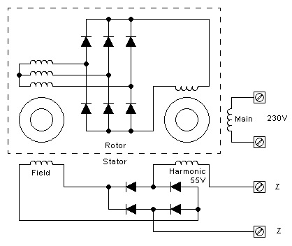 Merely the TFDW is a brushless synchronous generator, that is, instead of feeding the rotating field winding by means of carbon brushes and sliprings, it has a second generator mounted on the aforementioned shaft, called an exciter machine. This exciter has the field winding in the stator, and a three-phase winding on the rotor. Its output is rectified by a iii-phase span mounted on the shaft, and the resulting DC goes to the field winding on the rotor of the main machine.
As a result of this architecture, there are no brushes nor sliprings, eliminating the constant maintenance headache related to them. But the AVR for such a generator has a harder task to do, considering the generator has a ii-pole response: Both the field winding of the main machine and that of the exciter take a slow response, given by their high inductances. And in my TFDW generator both of them happen to have almost exactly the aforementioned pole frequency: 4.5Hz.
Two poles on the aforementioned frequency is somewhat of a problem to a controller. A proportional controller will make the arrangement oscillate, as presently as it has a decent proceeds. That'south what happens with the GB-160 AVR. A PI controller will also oscillate, if the P proceeds is loftier enough. A PID controller should exist able to control such a machine well enough. Simply at that place is a trouble: Since the output is an alternating voltage, it needs to be rectified and filtered to take a sample for regulation. And this filtering adds a third pole! If this third pole's frequency is inside the aforementioned club of magnitude as the machine'south two poles, nosotros will get an oscillator even when using a PID controller. And that filter'south pole cannot be very much higher than four.5Hz, considering it needs to provide good rejection of the rectified 50Hz signal (100Hz), and it cannot be very much lower than 4.5Hz, because and so the AVR's reaction to load changes would be too tedious! Then, we do accept a problem.
I intend to eventually design a "perfect" AVR for this type of generator, but for the moment, as a quick and dirty solution that works well enough, I decided to use the same old principle used in many AVRs over many decades: Brand a simple proportional controller, brand its phase delay every bit small as possible, and brand its gain just low enough and then the arrangement is stable. Then live with whatever voltage stability it produces. That's the AVR described in this article.
Harmonic and outphased excitation windings
The DC for the field winding needs to come up from somewhere, and an AVR needs to get powered in some style too. A simplistic approach is to use the 230V output for both purposes, and many commercial AVRs do simply that. In a benign environment (no overloads, no curt circuits, and with a speed-regulating prime mover) it works well plenty, only when the generator has to supply electric current surges, for example to start motors (compressors, refrigerators, electrical tools) it doesn't work so well, because when the surge happens and the voltage sags, the field current will too sag until the AVR has time to respond. This volition exacerbate the voltage drop caused by the overload. And in the case of a microhydro turbine driven generator, this is even dangerous: A short circuit at the output volition close off excitation, and then the generator volition end generating, and the turbine will go far overspeed. This tin mechanically destroy the machine, due to centrifugal force!To improve this, many generators have a special excitation winding on the main stator. This is not but a lower voltage winding working parallel to the main 230V winding, because if it were, its voltage would drib whenever that of the 230V winding drops. Instead it's either an outphased winding, typically wound in 90� phase relative to the main winding, or it is an harmonic winding, wound at 3 times shorter pitch than the chief winding. When there is a heavy load on the generator, the magnetic field in the stator distorts, weakens in the direction where the main winding works, and thus strengthens in the direction of the outphased winding, so that this outphased winding volition increase its output voltage. As well the harmonic contents of the field in the stator will increment, leading to a higher output voltage from an harmonic winding. And so, if a harmonic or outphased winding is used to ability the generator's excitation winding, this will tend to recoup for the load-induced voltage drop, only like in a compound generator. And in the effect of a brusk circuit, the generator will remain strongly excited. This gives such generators the power tu supply very large transient currents, for instance to starting time large motors.
The TFDW generator has both an outphased winding and an harmonic winding. I haven't investigated how they are connected, merely I assume that they are simply in serial. Nether typical operation, at nominal output voltage and almost one third the maximum load, my generator has roughly 55V on this winding. As shown in the generator schematic above, the output of this winding is rectified and applied to the field winding, with ii terminals named "Z" in between. I understand that an older version of this generator model had simply a rheostat connected to those terminals, to set the output voltage, while all load bounty was done through the effect of the combined harmonic and outphased windings. Later an AVR was added to provide a stable output voltage that doesn't require aligning, and this AVR in principle does't need to be very fast or to have high gain, because a skilful corporeality of load compensation comes simply from the utilize of these special auxiliary windings.
There are several models of AVRs for brushless generators on the market, such as the GAVR-8, GAVR-12 and larger ones, which don't apply these windings, instead taking all their ability from the master 230V output. While they should piece of work with the TFDW generator, I didn't desire to utilise any of them, mainly to avert the risk of a brusk circuit on the output causing excitation loss and allowing the rotation speed to run away, mayhap destroying the machine.
And so, subsequently all analysis of my generator model and of the available AVRs, I decided to build a new AVR that pretty much copies the same functionality of the original one, but in a simpler, more elegant and more reliable circuit. Although I don't think that galvanic isolation betwixt the generator's output and the excitation circuitry is necessary, the original AVR had this, so I designed the new one to have information technology besides.
The new AVR
 This regulator is an splendid instance of a very elementary excursion that works in a much more sophisticated way than what's credible at first sight.
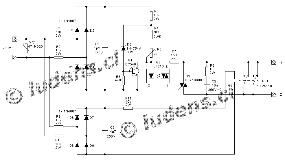
 Whenever the generator isn't running, or running very slowly, the relay is in resting position, holding the Z contacts closed. This allows the generator to cocky-excite equally soon as it reaches a sufficient speed. As the speed increases further, then does the voltage. Through D1-D4 and the resistors in that part of the circuit, the optoTRIAC volition get plenty input electric current to turn on equally before long as the generator'due south voltage exceeds roughly 40V. The zener diode is still far from conducting, and so Q1 stays off. As the generator's speed keeps increasing, and also its voltage, eventually the relay pulls in and opens the connection across the Z contacts, merely by this fourth dimension the optoTRIAC is solidly on, leading to the triggering of Q3, which keeps the Z contacts essentially joined past the TRIAC.
When the generator's voltage reaches the setpoint, at nominally 230V, the zener diode conducts enough current to cause a voltage drop beyond R6 that brings the transistor into conduction. At this bespeak the transistor will rob current from the optoTRIAC, which volition turn off. This leads to Q3 turning off on the next goose egg crossing of the generator's excitation winding's current. The circuit now goes into pulse-width-modulating mode: The voltage on C1 is a DC level with a significant amount of 100Hz ripple on information technology. This ripple makes Q1 change its conduction in such a way that the optoTRIAC turns on and off at a 100Hz rate, a pocket-sized modify of the generator's voltage causing a small shift on the DC level on C1, changing the amount of the ripple waveform that lies above the point that turns Q2 off, so that the duty cycle of Q2 varies from zero to 100% when the generator's output voltage varies over a few volt.
While Q2 gets 100Hz pulse-width-modulation, the field voltage follows this in a somewhat strange manner, since the generator'southward excitation winding outputs a mix of outphased 50Hz and 150Hz voltage, producing a waveform that changes with generator loading. Only this strangeness in the resulting voltage waveform doesn't cause whatever trouble, because it's happening at frequencies where the high inductance of the field winding performs a very good smoothing action. The field current is a pretty smooth and clean DC. The rectifier bridge in the generator non only rectifies the AVR-controlled Air conditioning into a DC, simply also acts a every bit a complimentary-wheeling diode for the field winding.
It has to be understood that this AVR does non regulate to a perfectly fixed voltage. Instead it regulates the output into a small voltage range, that is, the generator'south output voltage will drib by a small amount when the load increases. In most applications this is acceptable, and in some cases it'south fifty-fifty desired. If necessary this behaviour could be compensated or even overcompensated past compounding the 230V input to the AVR by ways of a suitable current transformer and load resistor that senses the generator'due south output current. Overcompensation tin be used to brand the generator increase its output voltage with load, to abolish the voltage driblet in long manual lines to the places where the free energy is used.
When the generator is stopped, the relay will drop and brusk out the Z terminals earlier the optoTRIAC turns off, thus the generator remains excited until it's running too slowly to cocky-excite.
An interesting detail is how thermal compensation is implemented in this AVR. Relatively high voltage zener diodes, like D5, suffer from a pretty strong positive thermal coefficient. If left uncompensated, the generator's voltage would rise in warmer weather, and would also rise while the AVR warms upwardly during utilise. So I compensated for this by using the much smaller negative thermal coefficient of Q1: When both D5 and Q1 get warmer, D5's voltage rises, requiring a higher voltage at its cathode. At the same time Q1's base voltage drops slightly, at the operating level where in average it robs just enough current from the optoTRIAC. The lower base voltage causes a lower current to flow through R6, which in turn reduces the current flowing through D5, and thus through R3, R1 and R2. The resulting lower voltage drop on those resistors provides the required college voltage at D5's cathode, while keeping the generator's voltage abiding.
For this thermal compensation to work properly, R6 must have the right value relative to the other resistors in the circuit, and Q1 and D5 need to be at roughly the aforementioned temperature. I implemented the latter by placing the transistor very close to the zener diode, keeping them reasonably separated from power resistors, and installing the AVR in my generator in such a position that D5 and Q1 do not become exposed to warm air rising from the parts that get warm, by and large the 4 input ability resistors and the relay.
 It's likewise very important to understand that the value of C1 is critical, and needs to be optimized for the generator's characteristics. If yous use this AVR for a generator different from the 10kW TFDW, you should absolutely try unlike capacitances, and pick the correct one. The capacitance value has two furnishings: One is that the smaller it is, the less phase lag it will cause, aiding stability and speeding upwardly the response. The other is that the larger it is, the more than gain the AVR will accept. More than gain causes tighter regulation, but beyond a certain value the organisation will become unstable and oscillate, typically at a few Hz.
In my original design I used 4.seven�F for C1, which is as well the reason why I used 4.7�F for C2 - simply to utilize 2 identical capacitors and thus reduce the number of different parts needed. That's also the reason why the 6 power resistors are of the aforementioned value - I tailored the circuit and then that I wouldn't demand to buy several different values of power resistors. R7 and R8 came from my junkbox, by the way, recycled from old TVs, equally their values are adequately uncritical.
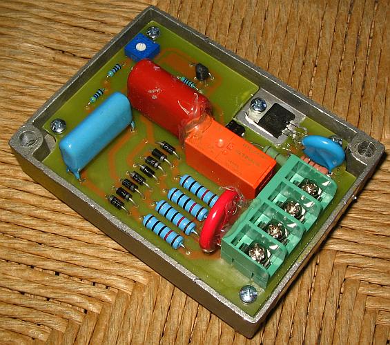
When I made the first test, with iv.7�F at C1, my generator oscillated. Not every bit bad as with the GB-160 AVR, but however it oscillated. So I started reducing the capacitance value. At i.8�F it still oscillated, at i.5�F it was marginally stable, and at i.2�F it was fully stable. So I kept 1.2�F, despite the fact that the only suitable capacitor of this value that I had at hand was a special loftier-current type with 4 terminals, a existent waste matter in this application! It's the large blue i in this photograph, which shows my AVR in its terminal form, set to be installed, complete with some hot glue immobilizing big parts that might otherwise vibrate.
If the value of C1 is changed by a large amount, R4 too needs to be inverse slightly, to keep the aligning range centered around 230V. With 4.7�F the correct value is viii.2kΩ. Below 1�F probably 10kΩ is needed.
To complete comments on the excursion design, I may add that R8 and C2 form a snubber network to aid TRIAC turn-off, and that most likely these are not necessary, just I added them for condom and peace of mind. R7 is sized to limit the worst-case trigger current pulse to a value that both Q2 and the gate of Q3 tin have, and if you apply this AVR with a generator whose excitation winding delivers a very different voltage than the 55V of mine, you should calibration the value of this resistor appropriately. The TRIAC is rated at 600V peak and 16A RMS, while the optoTRIAC is rated at 800V peak, so this AVR should be able to control pretty large generators. I used this oversized BTA16600 TRIAC considering I had some of them, they are inexpensive, widely bachelor, and have an insulated tab, which facilitates mounting.
Reliability
 Later having to hack the original AVRs out of their epoxy potting, due to iii failures in xi years, I wanted to make my pattern more reliable than that. I made a transformerless blueprint. The resistors have generous power and voltage margins. No electrolytic capacitors were used, because those are a very mutual cause of trouble in long-term use. To the extent possible the parts are used far below their maximum ratings. The rectifier diodes were placed backside resistors, and with capacitors across them, making them almost indestructible by voltage spikes. In add-on there is a varistor to clamp voltage transients, which may be unnecessary to protect this AVR, simply is useful to protect other parts of the system, and forestall flashovers. The original AVR instead has its diodes directly connected to the 230V input, without any protection at all, which caused their destruction by a transient from lightning hitting ground 600m abroad. The PCB was sprayed with acrylic lacquer after soldering, to preclude corrosion.
My main reliability-related worry is the relay. To avoid a transformer, the relay has a 110VDC coil with 29kΩ resistance, which is made from extremely fine wire. If anything corrosive gets at the soldered ends of this wire, it might easily corrode through and make the relay neglect. I considered using a relay with a 220VAC coil instead, which would let saving viii components in one strike and as well exist much more reliable thanks to the much thicker wire used in an AC relay coil, but I was worried that during generator startup and slowdown, at low speed and low frequency an Air-conditioning relay might chatter and become damaged. If you lot want to copy this AVR, and yous have a suitable 220VAC relay at hand, try it with your generator. If information technology doesn't chatter, employ information technology in place of my DC relay and its power supply!
I promise to eventually pattern an AVR for this generator that doesn't need a startup relay.
The PCB
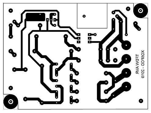 I designed this board specifically to fit the metal crush of the original AVR. Unless you are replacing an original TCEL CF-400 AVR and want to re-apply its shell, there is probably little point in exactly copying my board blueprint. Anyhow very likely some of your components will have different footprints than mine. But if you want to employ it, hither information technology is. Click on it to become the loftier resolution version.
 Delight note: At that place is a bug on this PCB! Pin 4 of the optoTRIAC is connected to pin ane of the TRIAC, instead of pin 2! I'one thousand getting old and I'chiliad starting to do stupid things, I know. I had to cut abroad that trace and replace it past a wire. And I was too lazy to re-design the board simply for publication on this folio.
Don't worry about the reversal of pin four and 6 of the optoTRIAC. That's not a problems, since those pins are totally interchangeable. Likewise it doesn't thing on which output concluding of the optoTRIAC R6 is. I privileged easy layout over slavishly following the mode I drew the schematic, and then I was too lazy to change the schematic accordingly! You will empathise, I hope...
R4 is split into 2 series-continued resistors on the board. This is because I didn't take any suitable 0.5W resistor at hand, so I used two 1/4W ones in serial, iv.vii and 4.3kΩ.
Note that all traces have proper clearances to the borders of the board, and those that have relatively high voltage betwixt them also accept that clearance between them. This is very important, and is something many newcomers to PCB blueprint tend to go wrong.
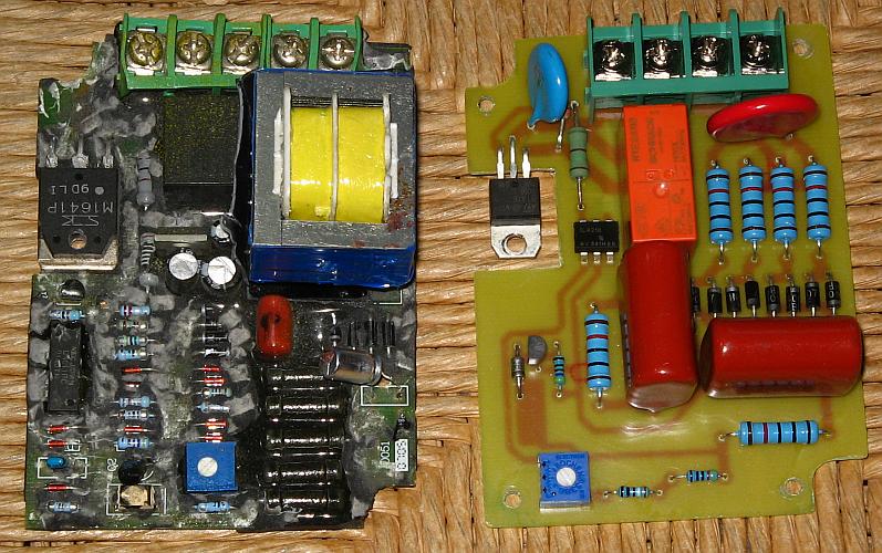
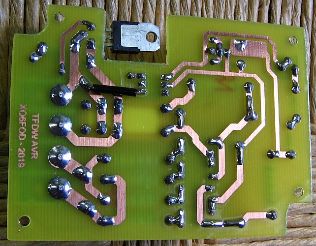 Hither yous can see the soldered PCB. Note that a generous amount of solder was used, and the terminals of big parts were bent over before soldering, to avoid failures from vibration. I used good old 60/40 tin/atomic number 82 solder, as I'm unconvinced of the reliability of atomic number 82-gratis solder.
You tin can see the location of the wire bridge that fixes the bug I made in the design.
I made this PCB by the photographic method, using presensitized board material bought on eBay, and printing the pattern with a cheap inkjet printer on Pictorico Ultra Premium transparency textile. That method is practical and works every fourth dimension. What I dislike is that the copper on these boards seems to exist very thin, and the board surface is groovy, and the copper too - simply it'south good enough to work. I demand to detect some meliorate quality presensitized board material for more demanding PCBs.
Recently I made some experiments with the toner transfer method, but with my light amplification by stimulated emission of radiation printer it just doesn't piece of work, neither using magazine paper nor using special transfer paper. And the results I take seen on PCBs fabricated by other people by the toner transfer method are poor, with attacked, porous copper traces. That doesn't happen with the photographic arrangement, and then I will stick to this for now.
Performance
The AVR is working cleanly, providing a significantly amend regulation than the original 1, thanks to its proceeds having been empirically adjusted as high as possible within stability constraints, past pick of C1's value. But there are still a few volt of droop when the load varies betwixt zilch and maximum. Not enough to have practical effects, though. As I write this spider web page, the generator with this AVR is powering my home.I would await this AVR to work with almost 230V brushless generators that have a separate excitation winding, be it harmonic, outphased, or a combination. It should be possible to apply it with a wide range of generator sizes, from the smallest all the way to 100kW and somewhat beyond. It can be used with 230/400V three-phase generators by sensing merely one phase, or the circuit could be modified past irresolute the sensing rectifier to a three-stage bridge and adjusting some component values. If this is done, C1 can be very much smaller for a given gain, due to the much higher ripple frequency and lower ripple aamplitude of a rectified iii-phase point, and this should allow higher gain and thus tighter regulation.
Of course it can also exist used with brush-type generators that accept an excitation winding, like the Chinese ST line. Since these are far less disquisitional regarding loop stability, I would propose to start testing with 4.7�F for C1 and 8.2kΩ for R4 (3.nine and 4.3kΩ in series, if you apply 1/four watt resistors). Virtually likely it will exist stable, and accept a droop of less than one volt.
Back to homo ludens electronicus.
espinozasunitoomas.blogspot.com
Source: https://ludens.cl/Electron/AVR2/AVR2.html
0 Response to "Can a Capacitor Generator Be Converted to a Automatic-voltage-regulator Generator"
Postar um comentário